
DIY - 555 Shift Light Buzzer
 07-05-2006, 10:58 AM
#1
VIP Member
Thread Starter

Join Date: Apr 2006
Location: Flagstaff, AZ
Posts: 50
Car Info: 05' PSM 2.5 RS Wagon w/ JDM Roof Vent
DIY - 555 Shift Light Buzzer

DIY 555 Shift Light Buzzer
Photos and Text by: Drew Brashler (yesitsdrew5310)
Disclaimer: Modification of your car involves risks and may void your warranty. I can not be held responsible for the modifications you consciously decide to undertake nor for the results of doing so.
Note: This modification was made to an Auto Meter Pro Shift Lite, other models installations may differ slightly.
Tools Needed:
- Philips Screwdriver
- Soldering Iron
- Solder
- Small Wire Clippers
Parts Needed:
- 555 Timer Integrated Circuit
- LM386N Integrated Circuit
- 8 Pin IC Lifters
- Small Speaker or Buzzer
- 2.2k Ohm Resistor
- 220 Ohm Resistor
- 10 Ohm Resistor
- 220 uF Capacitor
- 4.7 uF Capacitor
- 0.02 uF Capacitor
- 0.01 uF Capacitor
Jason from Rally Innovations sent me his Auto Meter �Pro Shift Lite� in hopes that I could make a circuit to make a loud annoying beep when the shift light goes off. He wanted it to be fairly small and have a switch to turn on and off the buzzer.
So, I knew I needed to have an oscillator to make the tone (or beep). That oscillator needed to go through an audio amplifier to make it loud.
I talked to my father about some ideas of how to make this work. We decided on a 555 Timer Integrated Circuit (IC) to make the tone and a LM386N Audio Amplifier IC to power a small speaker.
555 Shift Light Buzzer Schematic:
Here is the schematic I came up with for the buzzer. I took the positive and negative leads off the light bulb from inside the shift light to power my buzzer circuit.

Step 1 � Bread Boarding The Circuit:
I first setup the circuit on a bread board to test it out and make sure it worked. Once the circuit was built on the board, I plugged it into a 12v battery.


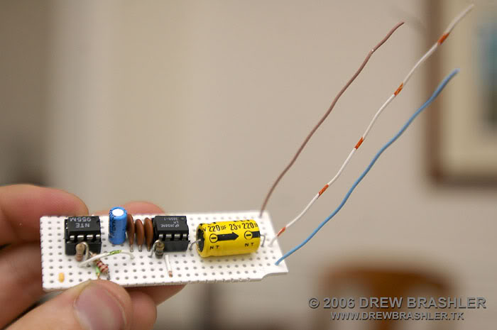
Step 2 � Building The Circuit:
Next step was to get a small circuit board to build the buzzer on. Once I found that, I started laying the parts out on the board. I then busted out my soldering iron and soldered the parts into place.


 07-05-2006, 10:59 AM
#2
VIP Member
Thread Starter
Join Date: Apr 2006
Location: Flagstaff, AZ
Posts: 50
Car Info: 05' PSM 2.5 RS Wagon w/ JDM Roof Vent
Step 3 � Fitting the Circuit Board:
I next grabbed a small saw to trim the circuit board to a smaller size to fit the enclosure that I wanted to put it in.
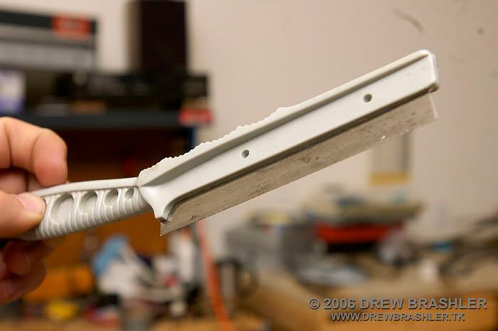
Here are two photos of the circuit board cut and ready to install into the enclosure.

Step 4 � Connecting To The �Pro Shift Lite�:
Next thing I did was to grab a Cat 5 network cable and use that to connect to the Shift Light. I needed to drill out some things on the light to make the holes bigger to make room for the wider cables. I then soldered two of the wires to the positive and negative terminals that give power to the light bulb. I also added zip-ties to make it look neat and tidy. After that was all done I put the light back together.


I next grabbed a small saw to trim the circuit board to a smaller size to fit the enclosure that I wanted to put it in.
Here are two photos of the circuit board cut and ready to install into the enclosure.
Step 4 � Connecting To The �Pro Shift Lite�:
Next thing I did was to grab a Cat 5 network cable and use that to connect to the Shift Light. I needed to drill out some things on the light to make the holes bigger to make room for the wider cables. I then soldered two of the wires to the positive and negative terminals that give power to the light bulb. I also added zip-ties to make it look neat and tidy. After that was all done I put the light back together.
07-05-2006, 10:59 AM
#3
VIP Member
Thread Starter
Join Date: Apr 2006
Location: Flagstaff, AZ
Posts: 50
Car Info: 05' PSM 2.5 RS Wagon w/ JDM Roof Vent
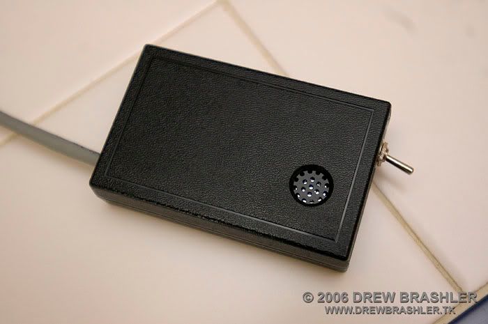
Step 5 � Building The Enclosure:
I used a Cat 5 cable to connect the shift light to the buzzer circuit, and I wanted to be able to disconnect the wire incase Jason, from Rally Innovations, needed to put the wire through his dash. So I added a Cat 5 connector and hot glued that inside on the bottom of the enclosure. I added a knot in the cable for strain relief.

Next I drilled a hole and hot glued a small buzzer to the top of the enclosure. I found the buzzer in an old 56k computer modem.


I then drilled a hole in the front panel for a on and off switch.

The Finished Product:
The buzzer works great. It is very loud and is a high pitch tone around the 5kHz range. I will post comments from Jason when he tries the new shift buzzer out in his car. Here are a few photos of the finished product:


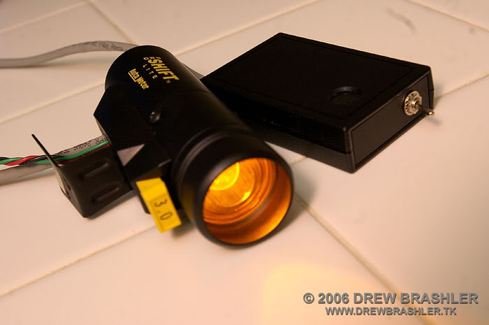
This concludes my DIY for making the 555 Shift Light Buzzer for the Auto Meter Pro Shift Lite. I hope this will help some of you out in trying to figure out how to build a shift buzzer.
Thanks for reading, and have a great day.
Drew Brashler
I used a Cat 5 cable to connect the shift light to the buzzer circuit, and I wanted to be able to disconnect the wire incase Jason, from Rally Innovations, needed to put the wire through his dash. So I added a Cat 5 connector and hot glued that inside on the bottom of the enclosure. I added a knot in the cable for strain relief.
Next I drilled a hole and hot glued a small buzzer to the top of the enclosure. I found the buzzer in an old 56k computer modem.
I then drilled a hole in the front panel for a on and off switch.
The Finished Product:
The buzzer works great. It is very loud and is a high pitch tone around the 5kHz range. I will post comments from Jason when he tries the new shift buzzer out in his car. Here are a few photos of the finished product:
This concludes my DIY for making the 555 Shift Light Buzzer for the Auto Meter Pro Shift Lite. I hope this will help some of you out in trying to figure out how to build a shift buzzer.
Thanks for reading, and have a great day.
Drew Brashler
 awesome write up though...very thorough.
 .
.


Thread
Thread Starter
Forum
Replies
Last Post
Bushflyr
How Tos / Installations
8
10-26-2007 07:39 PM
tekgnosis
Engine/Power - EJ20T (pre-2006 WRX and JDM)
14
09-07-2006 05:21 AM
HongKongBeef
Interior, Exterior & Lighting
3
07-12-2004 11:30 AM